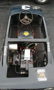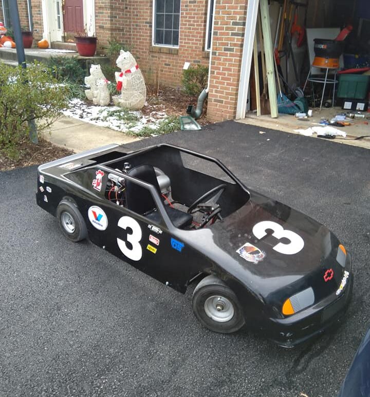
Growing up, my childhood best friend had a go kart for a brief period of time and I thought it was simply awesome. So when I was in senior year of high school, and trying to pick a major, I decided to give a shot to an engineering-type project. I hopped on ebay, bought a 1.8kW brushless motor, speed controller, throttle, and then hopped on craigslist, LetGo, and Facebook Marketplace looking for a donor chassis. I originally did a CAD model of my own chassis design, but with my inexperience in metalworking, I chose to buy an old donor. Lucky me, I found one for $100, and it was perfect. Brand new gas engine, which I could hold onto if I ever wanted to swap back or build another, fiberglass shell, all four tires, the thing was in really good shape – except for a bent axle! So what did I do?
I emailed a trailer shop. Of all places, I chose a random trailer shop that had done some work for my dad years ago (they wouldn’t remember, but I knew the business name at least) and asked if I could swing by on a slow day for them, for some assistance with straightening the axle. I added I would be happy to compensate for their time and tools, and we arranged a time to do it. Long story short, they put the entire kart up on a forklift, and we hit it with an acetylene torch until it was bright red! Super exciting for my 18 year old self, then we slipped a long metal pipe over the axle, and used the leverage to manually bend the axle back into shape. Sweet! The folks at the shop were super friendly, and loved to see a younger person trying to do a project, so they ultimately didn’t charge which was greatly appreciated. So then I moved on to getting the kart moving!
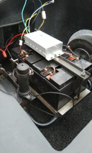
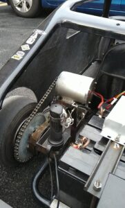
At first, I slapped together a wooden box that loosely ratchet strapped to the chassis. The box would hold 4 12V batteries in series, and if they were duct taped just right, they would actually stay in place. Then, not knowing what the original system used, I elected to purchase a motorcycle chain. Unfortunately, not only was this wrong for the motor, it was wrong for the axle sprocket as well, which meant I had to replace both. However, replacing both of them with a bigger, motorcycle grade part was the best choice (to me) because at the time I had no clue what forces were at play, nor how to do those calculations. I knew gear ratios and torque and such as concepts, but this was my first dive into a real project using them.

You can see the chain is not together, it had a tendency to slip off the sprocket and required adjustment!
With all that connected, and the ESC wired as best as I could (it came with no documentation), I set out and was able to do about 25-30mph in the kart! Honestly, I was thrilled. I would come home from school, and go around the block once or twice, with a huge grin on my face. The neighbors became familiar with the “whirring” sound the motor and chain would make, because it was unlike any go-kart they had ever seen! Afternoons where I would have the kart up on sawhorses in the driveway, passers by would stop in to ask questions, the mail man shared stories of their childhood kart, and it was an all around awesome experience. But then, college came, and I would be separated from my kart for some time, before coming back to revise it and upgrade to version 2.
Version 2
The wooden box was great, but it had to go. My uncle, thankfully, knew how to weld, so I took it up to him where he would teach me how to weld, and we collaboratively designed the rear end to have a) better battery mounts and b) a superior battery mount. Secret menu item C would be linking the throttle pedal to the throttle, which was still a handheld twist throttle meant for being on handlebars. Using the original throttle cable, which would control air/fuel mixture on the old engine, we welded in a bracket that kept the twist throttle oriented vertically, and added a linkage from a Vespa scooter to connect the cable to it. By adjusting the connection at the front, we were able to match the pivot of the pedal to the twist of the throttle perfectly, and unlock a true 0-100% throttle.
This was made better by a new speed controller, to replace my undocumented one which I unfortunately blew up while trying to add a “reverse” switch. The new controller had better instructions, which made it super easy to add a reverse toggle. It also had a higher top speed, but the only issue was that it was opposite of the orientation of the motor, so forward was backwards, and backwards was forwards – and backwards was faster than forwards! So after a few hours of googling, and watching some videos, I learned how to reverse the polarity of a three-phase brushless motor, and had myself a powerful little go kart.


Version 3
Version 3 is in the works now, but the main upgrade is a speedometer (which utilizes a hall effect sensor) to indicate speed of travel. Rather than an off the shelf variant, I chose to create my own enclosure, mount a 16×2 LCD in it, and have a sensor on the rear axle (drive tire side) send a signal once per revolution to an arduino Nano to then calculate and display the speed. In practice it worked okay, but I am revising the code due to a bug that prevents readings above 27mph from occurring. This is powered by a 48V to 12V step down unit, since the kart runs at voltage which is not ideal for accessories. The speedometer is installed, so I just need to update the firmware with the max speed bug fixed.

Additionally, after going on a late night ride on some trails around my university, I decided it needed some lights. So I have acquired two bright off road spotlights, and am working out how to mount them discreetly – ideally without modifying the fiberglass shell. Finally, I found some fun switches for forward/reverse from a kids power-wheels toy, and have set them aside to be installed when I do this Version 3 renovation.
