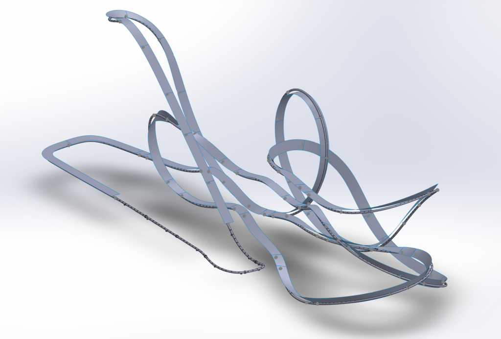
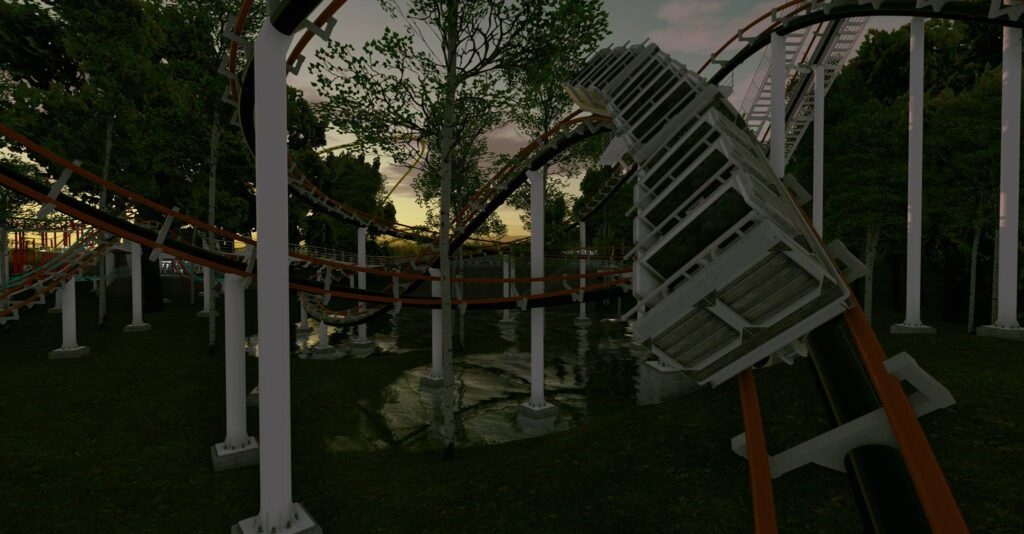
It all began with a software called NoLimits. Suddenly I found myself able to design and simulate roller coasters with a realism I had never encountered before! So I quickly threw together a layout inspired by those found at boardwalks, you know, where they try to incorporate the longest layout possible in a small space. Unfortunately, this was designed in freshman year after one semester of non-engineering classes, so in retrospect… The layout would need many modifications to even be physically possible. Not to mention the lack of supports. But this was a starting point for the project, the POV of the track is below:
The project was simple in theory; design the ride in NoLimits, export the spline, use a python script to split the exported data into track sections, and then use the new track section files to generate CAD models of the ride.
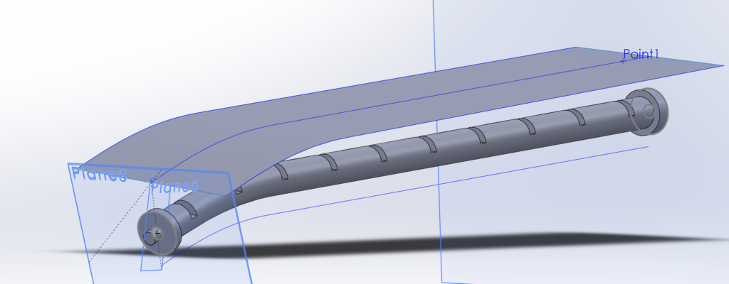
Shockingly, it went quite well. When imported into Solidworks, the entire track spline was loaded and the endpoint of one section would be the start point of the next – if it worked as I expected, it would be doable! So I set out using each 3D curve of the track to create a tubular spine of the track, and cutting slots into it on set intervals to later accept cross bracing to support rails. This process worked well, the only problem was the track didn’t line up at the end! I could, though, use mates in the assembly to make the circuit complete properly… It just wasn’t what I had hoped for, since it had to take advantage of the round couplers being able to rotate.

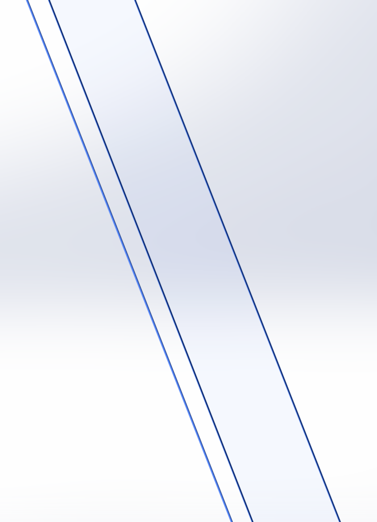
So what went wrong? It took me a long time to answer that question, actually, and to be perfectly honest I have not proven my theory correct yet. However this is my working theory: The manner in which I create the extrusions using the left, right, and spine rail curves as guides for some reason does not make it such that the flat surface on the end is coplanar with the plane created by taking the endpoints of each curve. Though it is only slightly off, it is extremely impactful when multiplied over the 50-100 track pieces!

The way I discovered this was by placing a plane defined by the surface of the end of the extrusion (a swept boss), and also placing a plane defined by selecting the 3 endpoints of the 3 curves defining the track segment, which is better seen here:


So, with the cause pinpointed… I simply have yet to find a solution I am happy with. I can simply create a boss extrude (or extrude cut) as needed to make it 100% coplanar despite the outcome of the boss, but since my goal with the project is to learn, I have been searching for a better solution. This project started in late 2018, when I barely knew solidworks. Now, in 2022, I am much more proficient and planning to revisit the project (it admittedly stalled after hitting this roadblock, and a month or so of trying without success to fix it). It could be as simple as my python code splitting the spline incorrectly, or a fundamental misunderstanding of guide curves. The Boardwalk Coaster is no longer the subject, though, I am actually looking at doing a mine train coaster!

Update: After spending an afternoon playing around in SolidWorks, the issue has become clear – the way in which solidworks defines the normal vector at the end of the line is good, but not perfect. So when I cut a line in half, the normal vector of the part before the cut and the normal vector of the part after the cut would ideally be equal and opposite, since one continues seamlessly into the next. However, they are not! This actually makes sense, as the vector would need to know what came next to be exact, so the solution to this will be to use an extrude and a cut to add a plate at the start and end of each section, and thus create a plane that is defined by our known normal. I still believe there has to be a way (perhaps using a loft, rather than a sweep) to get the start and end planes to be the exact way I need, but I’ll have to consult others to figure it out.
Now that I have the CAD figured out, I can go about the recreation of my mine train coaster layout with some modifications, and begin the process of converting the NoLimits model to a 3D printable CAD model. Using templates, and with some macros I hope to write in SolidWorks, it should only take a few hours to create the spine!
